Show Only...
×
For the best experience, please view this page on a larger device.

OK

Substation asset life extension


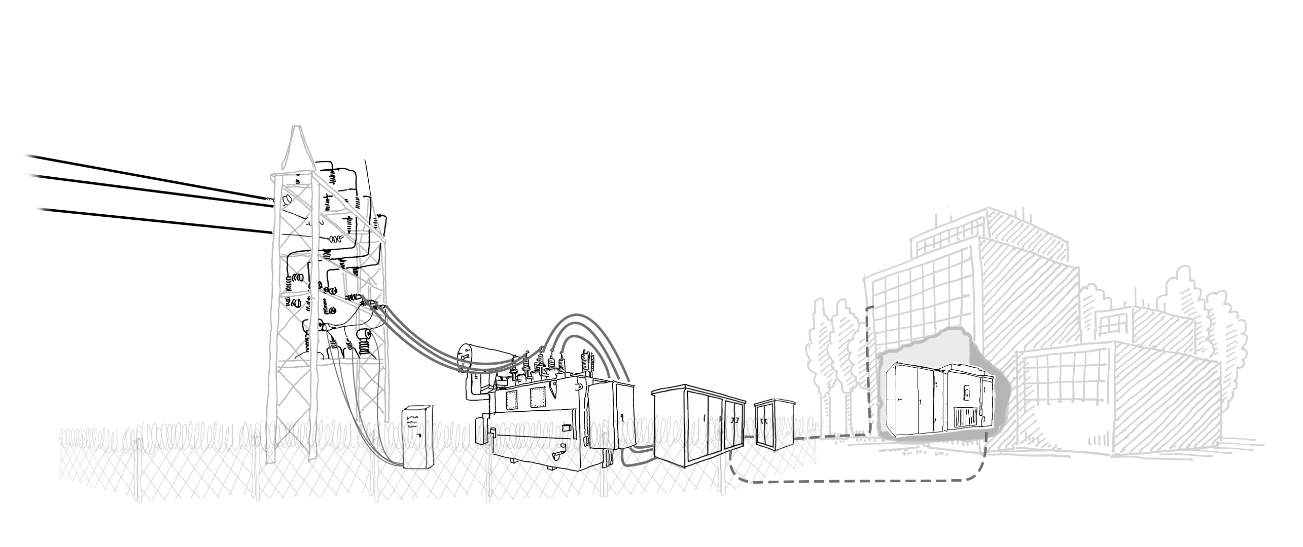
Your substation is a complex hub of high-voltage equipment that works hard every day to power your production. Do you know your critical substation assets? Do you have strategies in place for maintaining them?

Click on the substation components below to learn more about what they do, why they fail, and how you can prolong their reliable life.

Keep learning!

Here’s a not-so-fun fact. Industrial transformers have a life expectancy of 20–25 years, but more than 70 percent of U.S. transformers are already on borrowed time. Other substation components are only made to last a decade. Getting the longest reliable life from your substation assets is a complex endeavor. Feel free to browse our blog to continue your quest for substation knowledge.

GET IN TOUCH

Isolator Switch

Also called a disconnect switch or disconnector, this component is essentially a substation “off” switch. It isolates the substation from the utility feed with a visible gap that ensures a physical distance between the contact points. You’re likely already familiar with the isolator switch because it’s an integral part of the lockout/tagout (LOTO) procedure. Also worth noting, it has its own lightning conductor.

Failure modes

  • Insulation breakdown (due to voltage spikes, long-term overvoltage or lightning)
  • Handle mechanism wear/malfunction
  • Insulator wear/malfunction (supports the isolator switch)
  • Contact wear

Reliability considerations

  • Insulation breakdown (due to voltage spikes, long-term overvoltage or lightning)
  • Mechanical test of handle mechanism
  • IR scanning for insulators
  • Partial discharge (PD) measurements

Insulators

Insulators stop the flow of electricity. They prevent energized equipment from touching or arcing onto non-energized equipment, while also providing physical support for busbars, cables, and conductors. Often made of porcelain with steel fixings and cement binding, insulators are sturdy—yet still vulnerable to certain threats.

Failure modes

  • Extreme temperatures (can cause structural cracks)
  • Flashover (high temperatures, damage to porcelain)
  • Glazing defects (threatens insulation integrity)

Reliability considerations

  • Partial discharge (PD) monitoring
  • IR scanning
  • Visual checks for damage
  • Physical checks such as tapping and ring tests (when appropriate)

Current and potential transformers

Current transformers reduce current. Potential transformers reduce voltage. This provides the utility meter with a readable voltage.

Failure modes

  • Dielectric breakdown
  • Damage to bushings
  • Oil leaks
  • Overheating
  • Partial discharge (PD) breakdown

Reliability considerations

  • PD monitoring
  • IR scanning
  • Electrical tests
  • Visual checks for damage

Cables

Power cables are often overlooked and misunderstood. They are commonly confused with conductors, which you see coming from the utility into the substation. Cables, on the other hand, are inside of the substation, feeding power to your facility. Most of the cables in use today consist of plastic or rubber dielectric insulation and have already surpassed their 30 – 40 year life expectancy—making preventive maintenance paramount. The cables shown here are above ground, but your substation has cables below ground, too.

Failure modes

  • Moisture
  • Oxidation
  • Contaminated oil
  • Mechanical failure
  • Failure of insulation
  • Oil leaks
  • Short circuit
  • Interwinding Fault
  • Turn to turn fault
  • LTC
  • Bushing
  • Partial Discharge

Reliability considerations

  • Diagnostic testing
  • Remote monitoring
  • Moisture reduction
  • Oil Sampling
  • Infrared scanning
  • PD detection surveys

Find out more about...

Utility meter

A utility meter is similar to the meter in your home. It provides a measurement of how much electricity the substation has consumed. The utility meter is typically housed in a cabinet and represents the secondary (transformed voltage) feed from the current and potential transformers.

In terms of asset life extension, great news—the utility meter is one less thing for you to worry about! The utility company is responsible for the meter and will address any issues.

Bushings

Essentially, a bushing is like an insulating plug for your transformer. They allow electrical current to travel safely from the cable into the transformer’s tank, preventing the outer metal structure from becoming energized. Bushings are typically constructed of molded, glazed porcelain and can use mineral oil or synthetic resin bonded paper to increase dielectric strength.

Failure modes

  • Extreme temperatures (can cause structural cracks)
  • Flashover (high temperatures, damage to porcelain)
  • Glazing defects (threatens insulation integrity)
  • Pollution (contamination on the bushing surface can reduce the dielectric strength which can lead to deterioration and eventual failure).
  • Oil leaks
  • Partial Discharge breakdown

Reliability considerations

  • Power factor and capacitance electrical tests
  • Partial discharge (PD) monitoring
  • IR scanning
  • Visual checks for damage

CONTACT AN EXPERT


Why Power Factor Bushings?
Mike Horning explains how power factor testing can detect problems before that damage is done.

WATCH VIDEO 

Transformer

Your transformer takes its name from the fact that it “transforms” power. Its primary function is to step down the high voltages that come in from the utility (e.g. 23 kV) to levels more suitable for commercial use (e.g. 4,680 V). Also good to know, the transformer is the most expensive single component in your substation, so you’ll likely want to maximize its reliable life.

Failure modes

  • Moisture
  • Oxidation
  • Contaminated oil
  • Mechanical failure
  • Failure of insulation
  • Oil leaks
  • Short circuit
  • Interwinding Fault
  • Turn to turn fault
  • LTC
  • Bushing
  • Partial Discharge

Reliability considerations

  • Diagnostic testing
  • Remote monitoring
  • Moisture reduction
  • Oil Sampling
  • Infrared scanning
  • PD detection surveys

Find out more about...

CONTACT AN EXPERT

Switchgear

To use an oversimplified analogy, the switchgear is like the air traffic controller in your substation. It helps distribute power to various destinations, manage the electric load, and protect against faults. Consisting of a metal enclosure mounted with circuit breakers, fuses, and switches, the switchgear unit ensures the current flows where it should and at safe levels.

Failure modes

  • Loose connections
  • Overuse of oil circuit breakers (contaminates breaker oil, weakens dielectric strength)
  • Failure of potential transformers and current transformers
  • Short circuit
  • Fails to operate
  • Partial discharge
  • Overload

Reliability considerations

  • IR scanning
  • PD detection
  • Electrical testing

Find out more about...

Cables (below ground)

Power cables are often overlooked and misunderstood. They are commonly confused with conductors, which you see coming from the utility into the substation. Cables, on the other hand, are inside of the substation, feeding power to your facility. Most of the cables in use today consist of plastic or rubber dielectric insulation and have already surpassed their 30 – 40 year life expectancy—making preventive maintenance paramount. The cables shown here are below ground and are harder to access for maintenance.

Failure modes

  • Voltage transients
  • Damaged semiconducting layers
  • Overheating of the cable or insulation
  • Insulation cuts
  • Incorrect accessory/cable interface dimension

Reliability considerations

  • Eliminating physical and high load stressors
  • IR scanning (visible connectors)
  • Offline partial discharge (PD) testing
  • Reduction/elimination of overvoltage testing
  • Overvoltage monitoring

Find out more about...

Low voltage breakers

Located inside near your dry-type transformer, low voltage breakers protect against surges and faults as electricity is distributed throughout your facility. They are rated to a predetermined specification (typically 600 V or lower) and will “trip” when that voltage is met, disrupting the flow of power.

Failure modes

  • Mechanical faults
  • Seizing up
  • Overheating
  • “End of life” failure

Reliability considerations

  • IR scanning (via IR windows)
  • Visual inspections
  • Mechanical inspections
  • Alignment tests
  • Lubrication best practices

Find out more about...

Dry type transformer

True to its name, a dry-type transformer does not require fluid. It performs the same function as the transformer (converting electricity to usable voltages), but it’s better suited for low and medium voltage applications that don’t require as much cooling or dielectric strength. Typically you’ll see the dry-type transformer inside of your facility.

Failure modes

  • Insulation degradation due to moisture
  • Carbonization
  • Contamination

Reliability considerations

  • Power factor electrical tests
  • IR scanning (via IR windows)

Find out more about...

Transformer


What does liquid sampling tell you?
Liquid sampling is similar to when you get a blood draw at the doctor’s office. The technician sends your transformer’s sample to an analytical laboratory for a variety of tests. For example, dissolved gas analysis (DGA) examines the liquid’s gas profile to identify faults and their severity, while Karl Fischer (KF) moisture analysis gives critical information regarding the life of the transformer’s solid insulating paper. Liquid sampling is a necessary step in reliability-centered maintenance and can be made much safer with an external sampling device.

Cabinet Transformer


What does liquid sampling tell you?
Liquid sampling is similar to when you get a blood draw at the doctor’s office. The technician sends your transformer’s sample to an analytical laboratory for a variety of tests. For example, dissolved gas analysis (DGA) examines the liquid’s gas profile to identify faults and their severity, while Karl Fischer (KF) moisture analysis gives critical information regarding the life of the transformer’s solid insulating paper. Liquid sampling is a necessary step in reliability-centered maintenance and can be made much safer with an external sampling device.

Disconnectors


Why perform IR scanning?
Infrared (IR) scanning is a thermal imaging inspection method that can detect a variety of issues you never knew you had. Specialists can analyze the IR images to detect abnormalities that indicate overloads, unbalanced loads, low liquid levels, hot spots, and improper heat dissipation—all of which could lead to component damage or failure. IR scanning is a non-contact technique that can be made even safer with the installation of an IR window.

Cables


Why perform IR scanning?
Infrared (IR) scanning is a thermal imaging inspection method that can detect a variety of issues you never knew you had. Specialists can analyze the IR images to detect abnormalities that indicate overloads, unbalanced loads, low liquid levels, hot spots, and improper heat dissipation—all of which could lead to component damage or failure. IR scanning is a non-contact technique that can be made even safer with the installation of an IR window.

Current and potential transformers


Why perform IR scanning?
Infrared (IR) scanning is a thermal imaging inspection method that can detect a variety of issues you never knew you had. Specialists can analyze the IR images to detect abnormalities that indicate overloads, unbalanced loads, low liquid levels, hot spots, and improper heat dissipation—all of which could lead to component damage or failure. IR scanning is a non-contact technique that can be made even safer with the installation of an IR window.

Bushings


Why perform IR scanning?
Infrared (IR) scanning is a thermal imaging inspection method that can detect a variety of issues you never knew you had. Specialists can analyze the IR images to detect abnormalities that indicate overloads, unbalanced loads, low liquid levels, hot spots, and improper heat dissipation—all of which could lead to component damage or failure. IR scanning is a non-contact technique that can be made even safer with the installation of an IR window.

Transformer


Why perform IR scanning?
Infrared (IR) scanning is a thermal imaging inspection method that can detect a variety of issues you never knew you had. Specialists can analyze the IR images to detect abnormalities that indicate overloads, unbalanced loads, low liquid levels, hot spots, and improper heat dissipation—all of which could lead to component damage or failure. IR scanning is a non-contact technique that can be made even safer with the installation of an IR window.

Switchgear


Why perform IR scanning?
Infrared (IR) scanning is a thermal imaging inspection method that can detect a variety of issues you never knew you had. Specialists can analyze the IR images to detect abnormalities that indicate overloads, unbalanced loads, low liquid levels, hot spots, and improper heat dissipation—all of which could lead to component damage or failure. IR scanning is a non-contact technique that can be made even safer with the installation of an IR window.

Low voltage breakers


Why perform IR scanning?
Infrared (IR) scanning is a thermal imaging inspection method that can detect a variety of issues you never knew you had. Specialists can analyze the IR images to detect abnormalities that indicate overloads, unbalanced loads, low liquid levels, hot spots, and improper heat dissipation—all of which could lead to component damage or failure. IR scanning is a non-contact technique that can be made even safer with the installation of an IR window.

Dry type transformer


Why perform IR scanning?
Infrared (IR) scanning is a thermal imaging inspection method that can detect a variety of issues you never knew you had. Specialists can analyze the IR images to detect abnormalities that indicate overloads, unbalanced loads, low liquid levels, hot spots, and improper heat dissipation—all of which could lead to component damage or failure. IR scanning is a non-contact technique that can be made even safer with the installation of an IR window.

Utility responsibility


Who’s responsible for what?
This is a basic overview showing whether the utility or facility is responsible for each asset’s maintenance, reliability, and eventual replacement. However, please note that there can be additional scenarios. In some instances, for example, the facility may lease certain substation components, or the utility may own the transformer. In these cases, the responsibility for that asset depends on the service agreement.

Facility responsibility


Who’s responsible for what?
This is a basic overview showing whether the utility or facility is responsible for each asset’s maintenance, reliability, and eventual replacement. However, please note that there can be additional scenarios. In some instances, for example, the facility may lease certain substation components, or the utility may own the transformer. In these cases, the responsibility for that asset depends on the service agreement.

Isolator Switch Insulators Current and Potential Transformers Cables Utility Meter Bushings Transformer Switchgear Cables (below ground) Low Voltage Breakers Dry Type Transformer Disconnectors Cables Current and Potential Transformers Bushings Transformer Switchgear Low Voltage Breakers Dry Type Transformer Transformer Switchgear Facility Responsibility Utility Responsibility Utility Responsibility
Please wait while logging in.